| Difficulty Level: |
 |
fairly hard |
Parts and Tools
- Timber pieces:
- 300 x 100 x 12mm
- 550 x 100 x 12mm
- 100 x 50 x 12mm
- 480 x 70 x 12mm
- 75 x 40 x 70mm
- Long cylindrical magnet
- Drill and bit (same diameter as magnet)
- PVA wood glue
- Thin nails
- Hammer
|
- 1200/2400 turn coil (or insulated wire)
- 2x 1.5" screw or screw hook
- 50mm spring with strong 'loop' ends
- Thin but strong string x 1m
- Sandpaper
- Glue gun and glue
- Scissors
- 'Edspot' galvanometer or oscilloscope
|
Instructions
Seismometers are instruments which detect movement in the Earth's tectonic plates. They operate on the principle of inertia (a body at rest will remain that way unless a force is applied to make it move) and usually consist of a mass which is free to move and a sensor set up to detect the movement.
This guide shows how to construct a seismometer which incorporates an electromagnetic coil designed to pick up small movements from the suspended mass. The coil converts the movement into electricity which can then be displayed on an oscilloscope or galvanometer.

Fig 1: Approximate dimensions of the first three pieces of timber
Fig 1 shows the approximate dimensions of the first three pieces of timber. These need to be cut, sanded to remove any rough edges or splinters and then glued and nailed together. The timber can be either MDF or a softwood of around 12mm thickness.
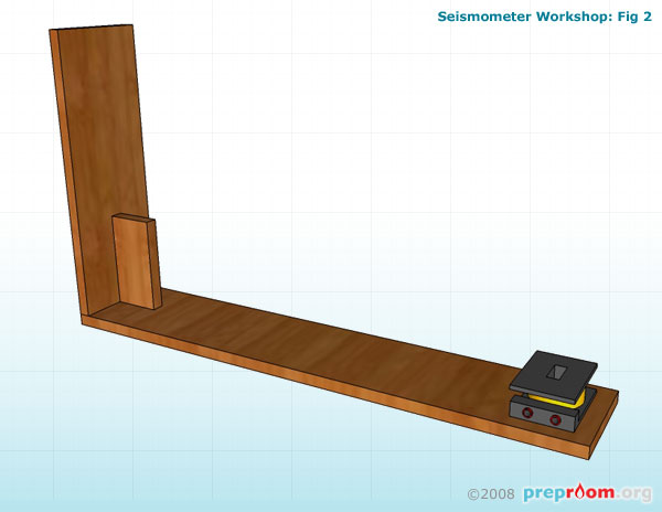
Fig 2: Location of coil
Fig 2 shows where to place the coil. The coil can be either a standard 1200/2400 turn type or a simple coil of insulated copper wire. Do not glue this in place yet as you may need to adjust its position slightly when some of the other parts are in place. This coil acts as a crude detector and combined with the magnet will convert the movement of the weighted arm into electricity.
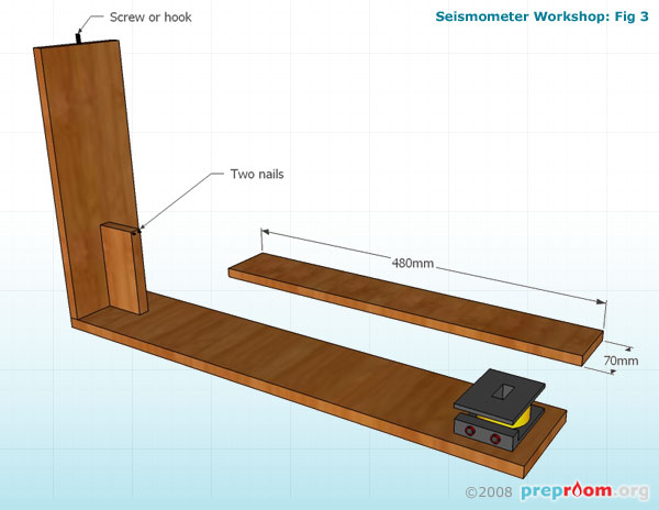
Fig 3: Dimensions of the arm
Fig 3 shows the dimensions of the arm part of the model. The arm will perch against the two nails pinned into the small upright section once the string holds it in place. At the top of the large upright section, screw in a hook or large screw where the spring will loop over and attach.
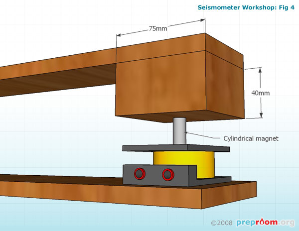
Fig 4: Block of timber glued and then nailed in place
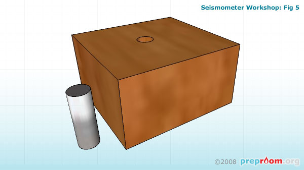
Fig 5: Block and magnet
Fig 4 shows the other end of the arm section with the block of timber glued and then nailed in place. The block acts as both a weight and also holds the magnet in place (see fig 5).
A hole should be drilled into the block which is the same diameter as the magnet. The hole may be opened up slightly using a screwdriver and the magnet glued into the hole using a glue gun. It needs to stick out of the block by about 3cm so a long cylindrical magnet works best. Attach the block to the underside of the arm using PVA wood glue and nails. The coil will need moving so that when the end of the arm rests against the two nails in the small upright piece, the magnet enters the hole in the middle of the coil. The coil can be glued in place once this is achieved.

Fig 6: Arm section in place
Fig 6 shows the arm section in place. Using scissors, take the string and tie it to the end loop of a spring. A spring with a loop each end is essential for this to work properly as the loops provide a secure way of attaching to the string and the model. Place the other loop of the spring over the hook on the large upright section. Tie the other end of the string to the other hook or screw which you need to attach to the other end of the arm (see diagram). Adjust the length of the string by wrapping it around the hook so that the arm sits level with the base as in the diagram. Ensure that both ends of the string are secure and the links between the string and the spring are also tight.
The coil should be connected to an 'Edspot' galvanometer or an oscilloscope using 4mm leads. When the arm moves up and down you should be able to see movement in the galvanometer scale or a small trace on the oscilloscope where electricity is being produced. The amount of electricity produced will relate to the amount of movement in the arm.
Disclaimer
Before attempting any of the construction projects featured on this website, ensure you have, and know how to use, the appropriate tools, components and safety equipment and are competent to undertake the project. These guides are for information only and we hold no responsibility for any accidents, injuries or damage caused by the use or misuse of any equipment, project or information contained within this website. In short - use common sense and stay safe!