This guide shows how to construct a mini Van De Graaff Generator. Although this generator is small in size, it is still capable of producing a harmless spark of around 2-3cm, given the right atmospheric conditions. This guide could be used by staff to construct a working demonstration model or by students as part of a physics/electrostatics project.
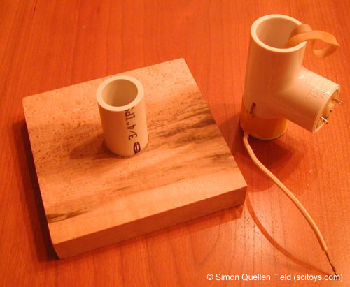
Fig 1: Start of construction
Fig 1 shows the start of construction. Firstly securely glue one of the PVC pipe lengths to the wooden base. This forms the base of the unit and will allow you to remove the main generator parts later to replace the rubber band or adjust the movement.
Flying leads need to be attached to the terminals of the motor before or after it is inserted into the 'T' section. It is easier to do this beforehand, unless you are intending to power the motor with a labpack and crocodile clipped leads. Wrap a small length of electrical tape around the motor body and insert it into the 'T' connector. The tape will help hold the motor in place securely. The generator works better if you wrap a small amount of tape around the motor shaft to increase its diameter slightly, or if you have a suitable motor pulley that will fit the shaft to incorporate the rubber band, that would also work. Wrap one end of the rubber band around the motor shaft and leave the free end poking out of the top of the 'T' connector.
Drill a small hole in the side of the 'T' connector just under the motor shaft and insert one of the lengths of multi-core wire which has been stripped of around 1cm of insulation. The bare ends of the wire should just touch the rubber band, without rubbing too much. Secure this wire with some tape rather than glue so that it could be replaced or adjusted later if required.

Fig 2: PVC inserted into the 'T' connector
Fig 2 shows the other length of PVC pipe having been inserted into the 'T' connector. You may have to cut the length of this piece accordingly to accommodate the length of your particular rubber band. It is essential that the band is taught enough to move when the motor is started yet not too tight as to slow down the motor. Insert the nail in the loop of the band to hold it in place for the time being.

Fig 3: Cut a hole in the centre which will snugly fit around the ¾" pipe
Cut the bottom off of the polystyrene cup, around 3-4 cms from the base and cut a hole in the centre which will snugly fit around the ¾" pipe. This should fit into place as in Fig 3. you can glue this later.
Take the PVC coupler piece and drill three small holes near the top. Through one of the holes insert the second piece of multi-core wire, again, one end stripped of insulation and secure with tape. The other end of the wire must also be stripped this time as it will be this end that comes into contact with the can, electrically connecting it to the top brush. The other two holes should be made opposite each other so that the nail can act as an axle for the top of the rubber band.
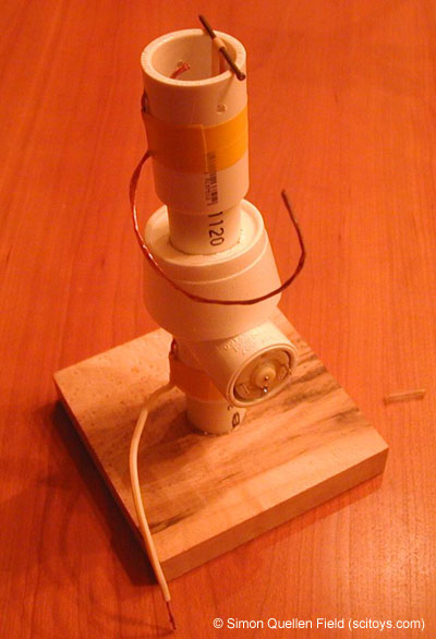
Fig 4: Coupler in place
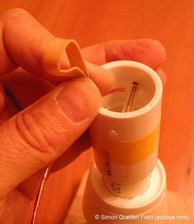
Fig 5: Glass tube free to rotate around the nail
Fig 4 shows the coupler now in place. Take the small glass tube, having cut it to size and heated each end so that there are no rough or sharp edges, and place it over the nail while also securing the nail in place through the two holes in the coupler. This is quite fiddly because you also need to move the rubber band onto the tube also. The glass tube should be free to rotate around the nail. See Fig 5.
Fig 6: Polystyrene cup glued into place
Fig 6 shows the polystyrene cup having been glued into place. This will both hold the can in place and insulate it from the base.

Fig 7: Cut the top off of a standard empty drinks can
In Fig 7 we have cut the top off of a standard empty drinks can. This can either be done using a can opener or with a knife. If using a knife, take great care and wear cut-proof gauntlets. Make sure there are no sharp edges left anywhere on the can, removing burrs with a round file.
Tuck the free end of the top wire into the can, ensuring it touches the inside surface and place the can onto the polystyrene collar so it sits securely.
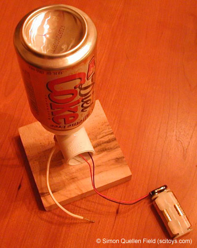
Fig 8: Battery connector in place
Fig 8 shows the battery connector in place. Two AA batteries provide the power to the motor. Alternatively a Lab Pack supplying 3V could be used.
To run the unit, connect the batteries or power supply while holding the free end of the lower brush. You should feel a small spark from the top of the can when touched with your other hand. The unit works in exactly the same way as a standard Van De Graaff generator, just no a smaller scale. Although smaller Voltages are created by this unit, health and safety guidance for standard sized Van De Graaff generators should be adhered to.
Because the exact design of the model will vary, some trial and error may be required to get the best output from this device. Adjusting the brushes closer or further from the band would be first on the list if no spark is present. Adjusting the speed of the motor by increasing the Voltage could also help produce a larger spark. Some rubber bands are also coated with resin which may affect performance and some drinks cans are coated with heavy paint which may affect their electrical insulation.
All photos are © Simon Quellen Field (scitoys.com), used with permission.
Click here for more information about the Van De Graff Generator.