This is a very simple guide which shows how to construct a set of transmission lines, used in physics lessons to demonstrate how electricity is transmitted along wires.
These transmission lines should only be used to carry a maximum of 12V and should never be connected to mains voltages. Only ever use low voltage labpacks which provide a maximum of 1V.
Each end of the transmission wire needs to be securely held in a clamp and stand for this demonstration and therefore is a good idea that the ends of each line has a sturdy length of dowel as its main component.
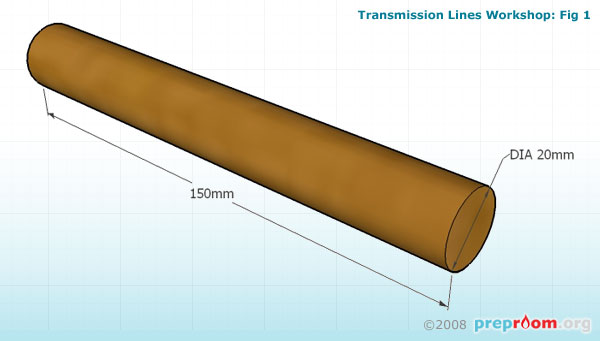
Fig 1 shows the dimensions of the dowel used in this model. The size can vary to suit your needs and the size of the clamps you will be using. The lengths should be cut and sanded to remove any splinters. Two lengths of dowel will be required.
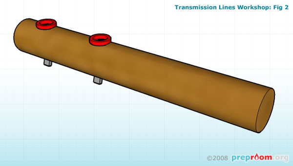
Fig 2 shows the two 4mm sockets in place. Firstly the dowel needs to be drilled in two places at least 35mm apart. The size of the hole required will depend on the type of the socket you are using. Most require a 4mm hole but others may require a larger hole so check the recommended hole size for the socket you will be using.
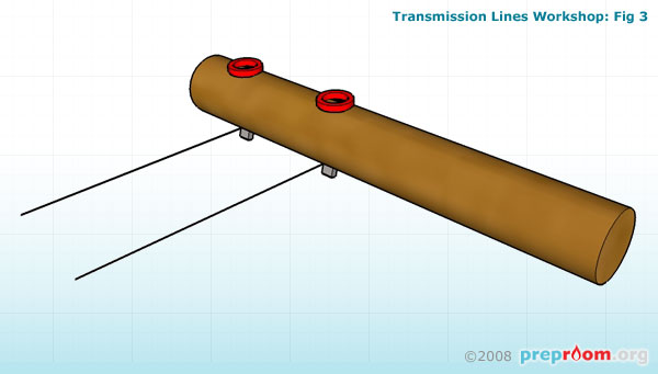
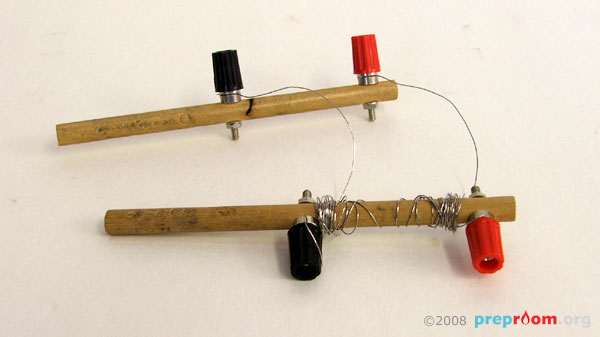
Fig 3 shows the nichrome wire connected to the sockets. With the simple socket type in the diagram, the wire needs simply to be looped several times around the base screw to achieve a secure and conducting join. Alternatively you can use the bigger socket and screw type as in fig 4 which makes it a lot easier to secure the wires. In this case the wire can be inserted into the holes and the screw top applied.
The length of the nichrome wire needs to be approximately 1m although follow the demonstration instructions which are usually found in text books closely.
The transmission lines may be connected to a transformer or power supply using standard 4mm wires.