This guide shows how to construct a model reed switch. The switch works in exactly the same way as a standard electrical reed switch but is much larger and so can be used to demonstrate how the magnet activates the switch in clearer detail.
Reed switches are often used in proximity sensors and burglar alarms and usually consist of a small glass envelope with two metal strips inside. When a magnet is brought close to the envelope, one of the metal strips bends slightly in the magnetic field and makes physical contact with the other metal strip. In essence the device acts as a push switch and can be inserted into circuits like any other type of switch. In this model the steel strip will be attracted by the magnet and will bend to make contact with the aluminium strip. As aluminium is non-ferrous, it should stay rigid when a magnet is placed close-by.
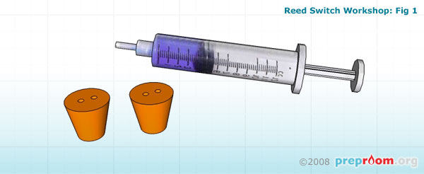
To make the model reed switch, you will need a large plastic syringe that can be cut up and two double-holed bungs which will fit into the cut ends (see fig 1).
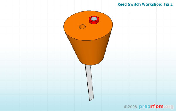

Each of the two bungs need to be constructed in similar ways. Firstly solder a short length of insulated copper wire to each of the two 4mm sockets and insert one into each of the bungs (see fig 2). In the other hole of each bung, on the opposite side to the 4mm socket opening, insert the strips of metal. One should be aluminium and one steel, both need to be the same size and shape but the aluminium strip needs to be sturdier than the steel one. They should be long enough to be approximately three quarters the length of the tube (see fig 3). The steel strip needs to be flexible enough to bend when the magnet is brought near so you may want to test the flexibility of the strip before inserting into the bung.
The free end of the copper wire needs to make contact with the metal strip in each bung. This can be soldered into place (although the aluminium part cannot be soldered without special solder), held firmly in place with each metal strip or glued into place ensuring a good contact.
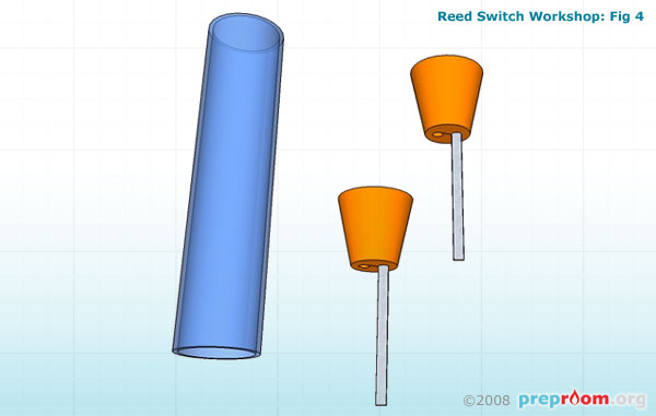
The syringe needs to be as large as possible so that the internal workings can be seen easily. Using a small hacksaw, gently cut the ends off of the syringe and file down any rough edges with the round file. Try not to scratch the sides of the tube with the file to ensure the tube remains transparent (see fig 4).
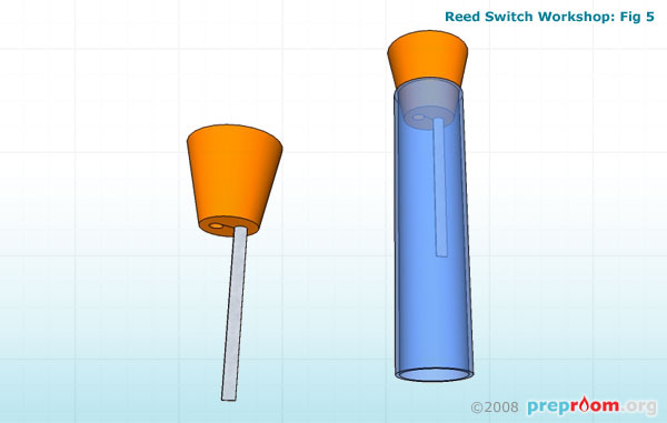
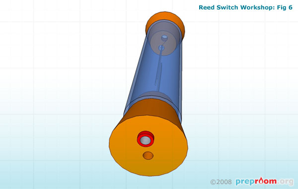
Fig 5 shows how the two bungs should be inserted into each end of the tube. The fit should be as tight as possible. A small dab of glue can hold the ends firmly in place but test the switch works before committing to this.
The metal strips should line up to face each other in the tube and should sit as close as possible to each other (see fig 6). The closer they are to each other, the easier it will be to activate the switch with the magnet.
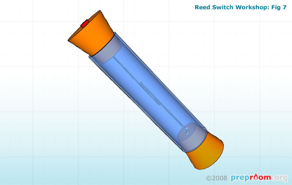
Fig 7 shows the finished model. This can be attached to circuits using standard 4mm connecting leads and can be optionally mounted on a board using mounted pipe clips.
A strong magnet can be used to activate the switch although if a very thin strip of steel is used you may only need a weak magnetic field for activation.
A standard reed switch can be included with this model to show the size difference and a flexcam and/or microscope used to show how the real reed switch operates in the same manner as the model.