This model represents an electromagnetic bell and shows how a simple electromagnet can make a steel strip oscillate.
Model bells have been made in schools for many years to demonstrate how the electromagnet can open and close a switch and how this movement can be used to ring a bell. Usually a hacksaw blade and a coil of insulated wire is used to make a temporary model. This guide shows how to construct a more permanent model which may be used many times over without need to set up each time. It also looks more attractive and shows each component part clearly.
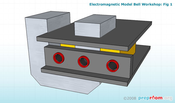
Fig 1 shows how the coil is attached to the 'C' core. 1200/2400 ready-made coils can be purchased from most lab suppliers. Alternatively a coil of plastic coated copper wire can be attached to one side of the core. It will perform exactly the same function although the ready-made coil looks neater and because it consists of many more turns than the copper wire coil, it will work better at lower currents.
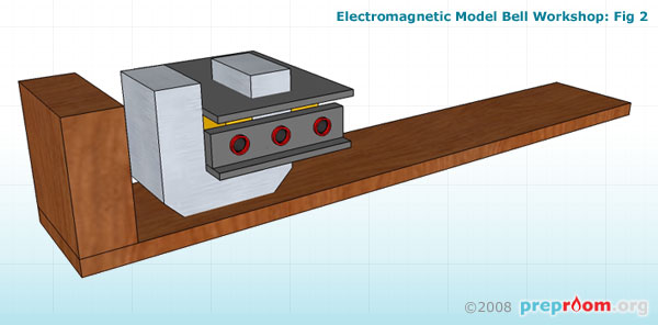

In fig 2 the coil and core are attached to the large timber piece using a glue gun. At each end of the base, attach one of the small timber pieces using PVA wood glue and thin nails (see fig 3). The wooden end pieces should be the same height as the top of the 'C' core.
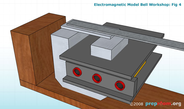
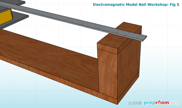
Fig 4 and fig 5 show how the long steel strip should be attached. One end of the strip should be attached securely to the far end piece of timber as in the picture. A small piece of timber may need to be attached to the existing upright piece to ensure the steel strip sits just above the 'C' core at the other end. Alternatively just bend the strip up slightly. The steel strip should be of the type which can be bent but remains slightly springy. This strip will flex up and down when the electromagnet is powered so also needs to be light enough to move easily. A few nails should be tapped through the strip to hold it in place. The strip needs to overhang the end slightly so that wires can be connected using a crocodile clip.
At the 'C' core end of the steel strip, attach the smaller steel/iron piece using a glue gun and/or tape. This will act as the electromagnet 'keeper'. Make sure both strips touch each other so electricity can flow through one to the other.
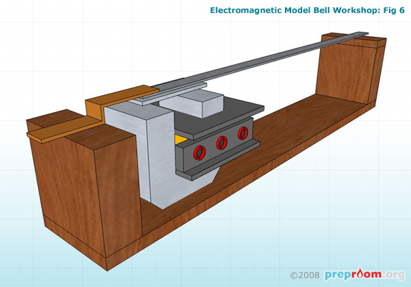
Fig 6 shows how the copper strip should be attached. This strip should be very thin and should be able to flex. This acts as the switch contact and needs to be positioned so that it just touches the top of the steel strip. The other end needs to overhang slightly so that a contact can be made using a crocodile clip.
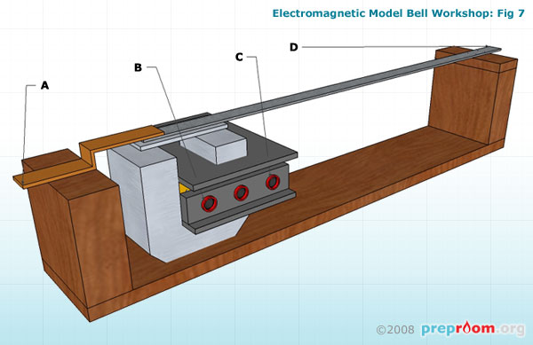
Fig 7 shows how the parts should be connected electrically. Connect A to B together using a connecting wire and crocodile clip. C and D need to be connected to a low voltage labpack. Connect to as low a voltage as possible in order for it to work. 1V D.C from a L.V labpack should be sufficient. Certainly do not exceed 6V.
A little trial and error may be required to get the steel strip moving up and down. Make sure the copper contact just about makes contact with the top of the steel strip.
As the copper part makes contact with the steel strip, the circuit is closed and so the electromagnet activates. This pulls the steel strip towards the 'C' core, breaking the circuit. With the circuit broken, the steel strip springs back up to once again make contact with the copper strip.
It is this movement which enables a bell hammer to ring the bell.